Unity Shader Graph retro-style clouds
I was in need of some rather simple clouds for my Unity project. I was specifically looking for clouds that would look good in a night time setting. I wanted them to be easily configurable so that I could have different skyboxes per scene without actually having to draw additional skyboxes. My game is inspired (but not limited) by early PlayStation graphics. I could have gone in multiple directions with that in mind. I went with a rather simple solution, randomly generated noise on a plane. There’s many resources on the internet that lay out how to achieve a similar effect, but none that did quite what I wanted. So let this be another!
The shader
For the sake of this page I will go with the assumption that you have some basic knowledge of Shader Graph, enough to re-create my set up from screenshots alone. I will go over what the shader looks like and what it does, as well as some choices I made.
The final shader will end up looking like this. Don’t worry, zoomed in screenshots are below. This shader is applied to a material on a flat plane positioned in the sky.
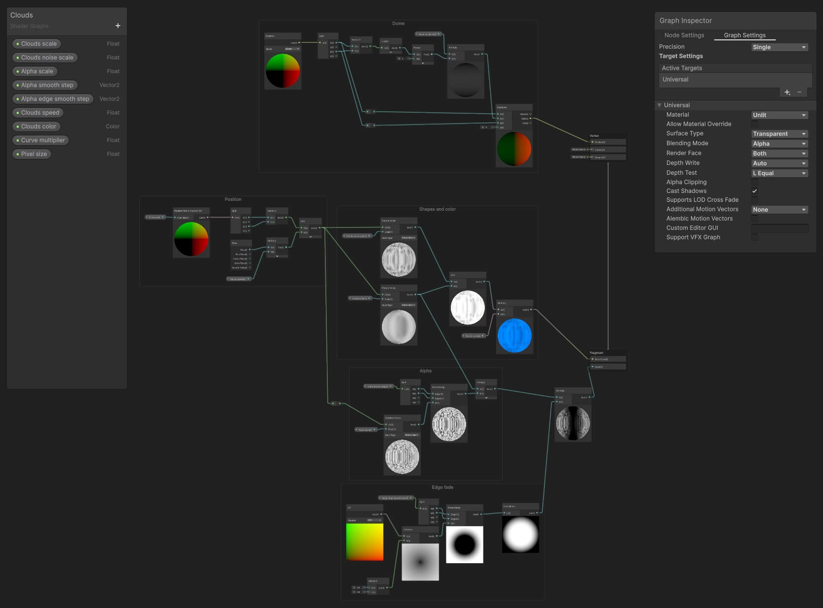
Clouds
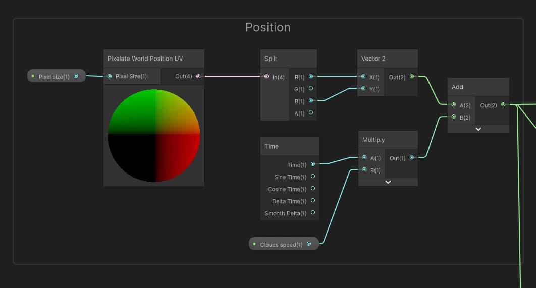
The first step is generating noise, moving that noise with time, and applying a color to the final result. Let’s start off with grabbing the position for where the clouds will appear. This uses a UV position node. In this case I am using a custom sub graph named “Pixelate World Position UV”. I will get into pixelation later, but for now you could replace this subgraph with a Position node set to World, the rest of the graph will look the same. This node is split into two components, the X and Z axis only, which are fed back into a Vector 2 node. We only need the X and Z components since the clouds will only move horizontally, there is no vertical movement.
To move the clouds we add a Time node and multiple the Time value with a variable that determines the speed, simply named “Clouds speed”. We add the result of this and the previous Vector 2 node together to get our position. This will be fed into several other nodes requiring a UV.
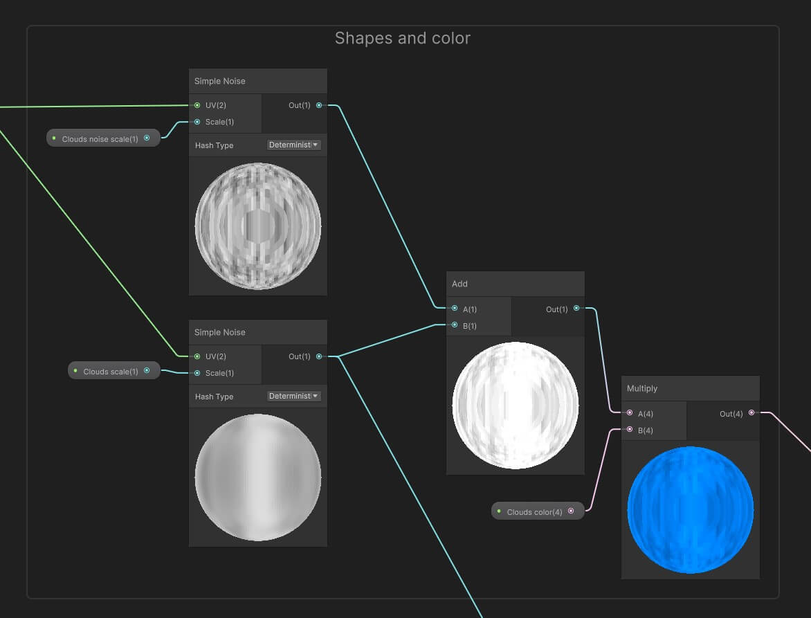
With the UV set up we generate two noise patterns. For both we use Simple Noise as this creates the most random noise patterns without islands. One of the Simple Noise nodes will use “Clouds scale” as its scale, the other “Clouds noise scale”. The first variable determines the overall size and shade of the clouds, the white bits, the second determines smaller details and shadows within the cloud. “Clouds scale” will be set to a small value around 0.05-0.1. A smaller value will mean you get larger clouds, a larger value will result in a much noisier appearance which might be neat when trying to create rain or storm clouds. “Clouds noise scale” is set to something about 10 times higher, along the lines of 0.2-1, creating more detail within the cloud. Both of these are added together and finally multiplier by a “Clouds color” value. This is used to color the final result, as you might have inferred. This is useful to create darker clouds or different colored clouds during different periods of the day.
The final result of the multiply is plugged into the “Base Color” of the fragment section, and that’s our colors done!
Alpha
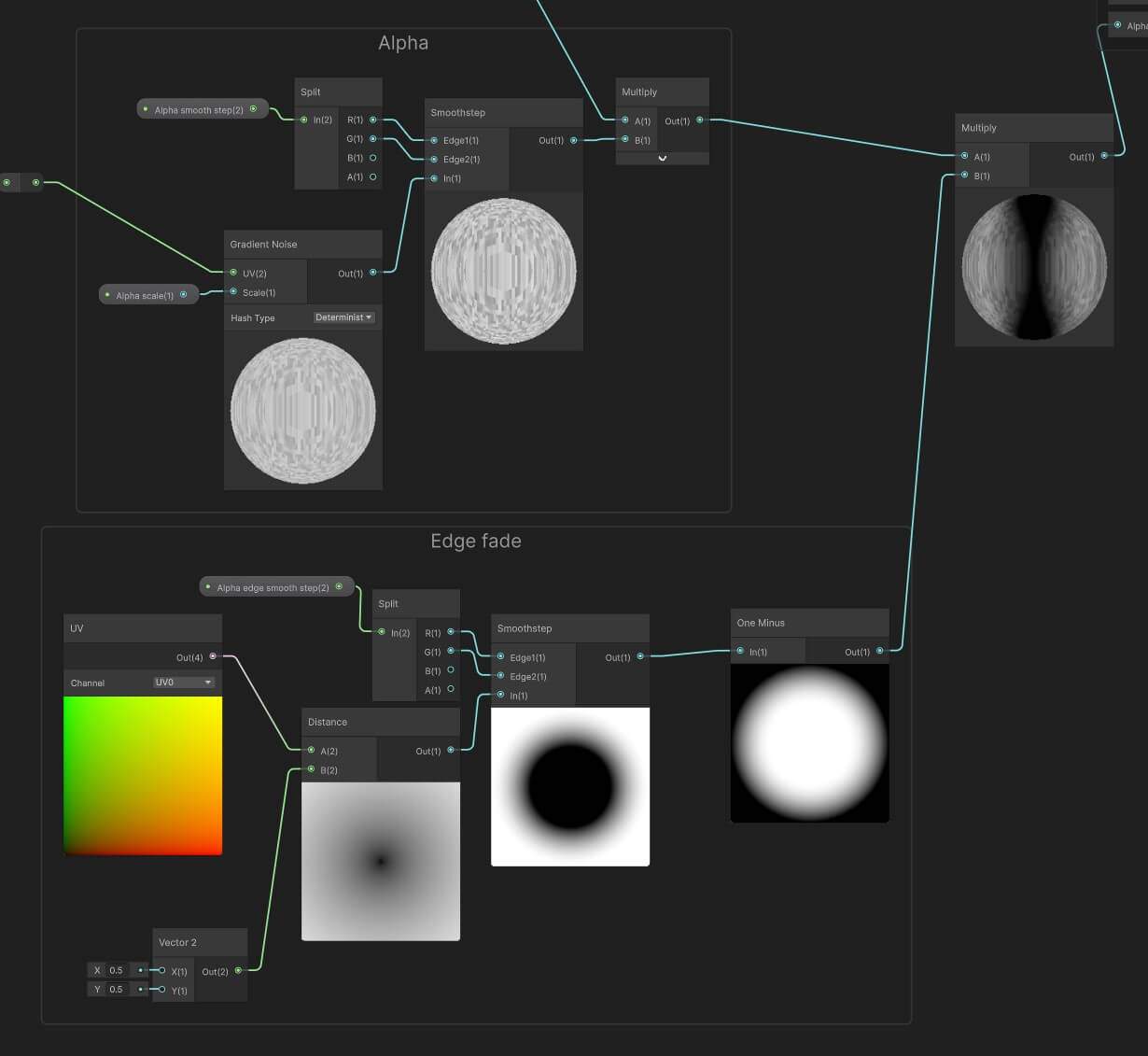
What we have so is a constant layer of clouds across our sky with nothing of the clouds showing through. First up we’ll create a new noise node, this time using Gradient Noise as this allows us to nicely create individual clouds, rather than one continuous sky. The Gradient Noise is fed the UV we created early as well as an “Alpha scale” value that will determine the size of the individual clouds. This is fed into a Smoothstep node. This node allows us to essentially adjust the contrast and gradient of each cloud. For instance setting a value of x=0.1 and y=0.2 will create very clear gaps in a fill sky, x=0.7 and y=0.8 will do the opposite, create very defined clouds. Larger deltas will create much smoother transitions. x=0 and y=5 will create very soft transitions. Play around with these values to see what works best for you.
This smoothstep is multiplied by the “Clouds scale” simple noise from earlier. This is optional but helps breaks up patterns and helps make the alpha look more in line with the clouds themselves.
The edge of the plane will show a clear cut-off line from which the clouds appear (more on this later!). The first step to alleviating this issue is adding a fade along the edge. For this we add another UV to get the Distance of each pixel to the center. We feed this into another Smoothstep, here the “Alpha edge smooth step” value is used to determine the harshness of the transition. Once again, see what values work well for you. This is fed into a One Minus node, which simply inverts the previous node.
The output of the Alpha and Edge Fade blocks are multiplied together and fed into the “Alpha” of the fragment section, and with that we have well defined clouds!
Hiding the edge
We apply our material to a flat plane high up in the sky, but when looking far into the distance the end of the plane is quite clearly visible. This is alleviated somewhat by the edge fade we set up, but that ends up with sky in the distance having no clouds at all.
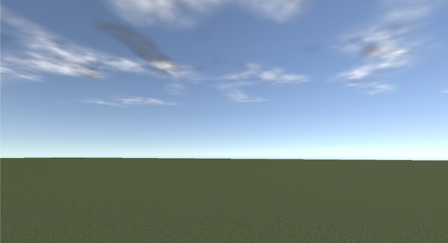
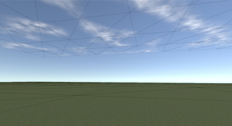
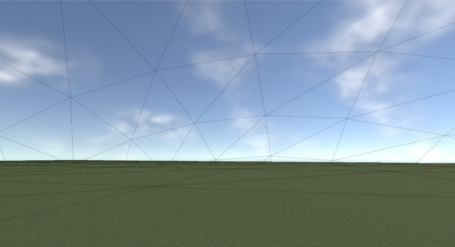
We could make our plane much larger, but if we have a rendering distance set that won’t help much. Instead we will be changing the position of the vertices to create a dome-like shape.
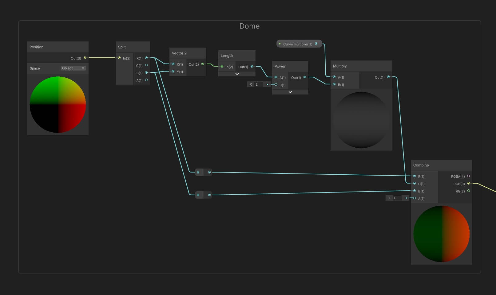
First up we get create a Position node set to Object. Our plane has no height, so all we want are the X and Z value, which we get from the Split node. We feed both of these into a Vector 2 node to combine them and feed this into a Length, getting the magnitude of our vector. This is fed into a Power node, which will displace each vertex by their position. To control by how much we multiply this by a “Curve multiplier” value. This will by a small value around 0.05 and 0.1, depending on how large and high up your plane is. This output is the final Y value of each vertex and is fed into a Combine node, combined with the same X (R) and Z (B) values from our Split from earlier, getting the final XYZ value of each vertex. This then is fed into the “Position” of the vertex section.
Pixelation
For my particular use case I wanted the clouds to be showing clearly defined pixels as that fits the style of my game. This might not apply to your game, in which case you can simply use a Position node set to “World” as mentioned earlier, in which case, you’re done!
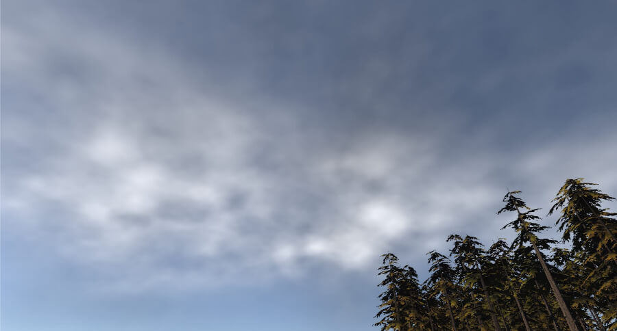
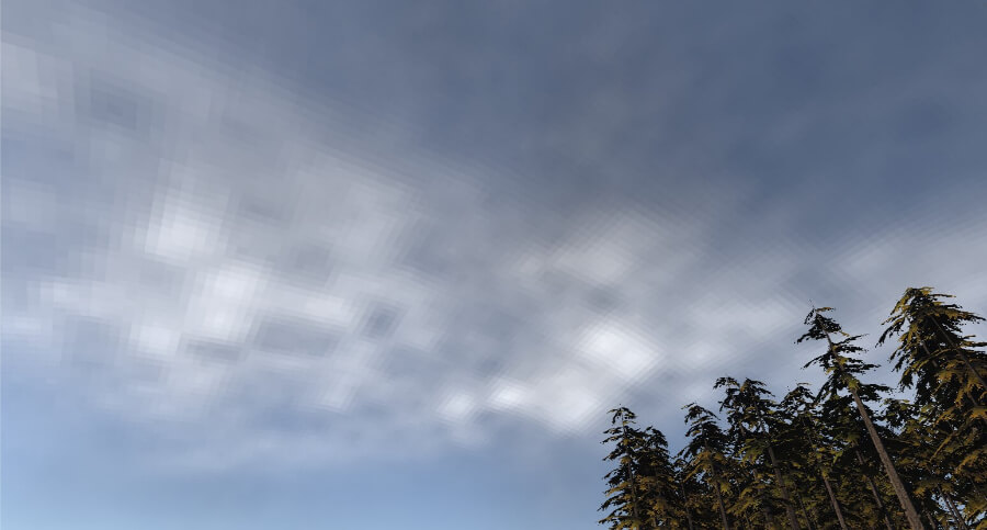
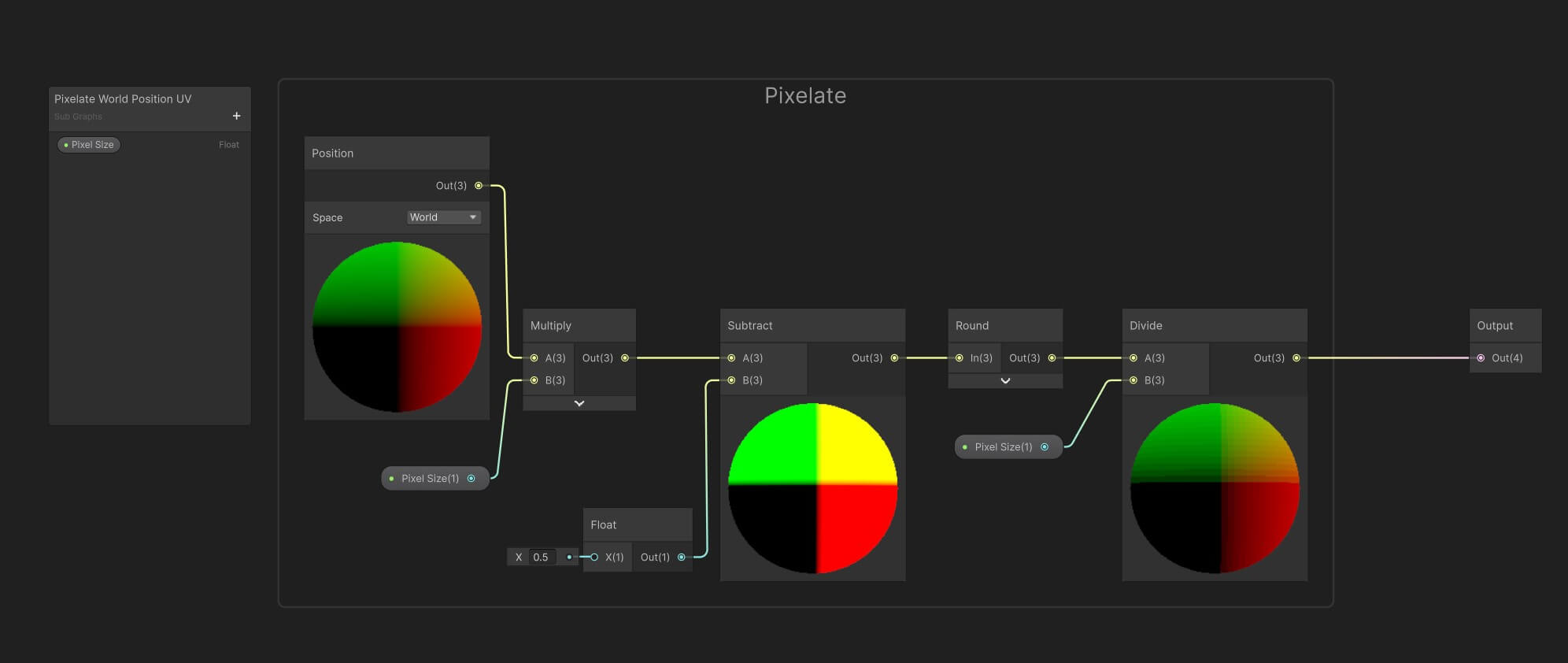
Pixelation is something I use throughout more graphs and I’ve opted to use a Subgraph to avoid repetion. This has a single variable “Pixel size”, where a lower value means larger individual pixels.
We grab a Position node set to “World”. This is multiplied by the “Pixel size” value. From here we subtract the value with 0.5, centering the UV. This value is rounded and divided by the same “Pixel size” value, rounding each UV coordinate to the nearest pixel value. This subgraph is than used instead of any World Position node.
Final material
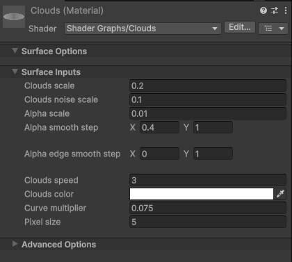
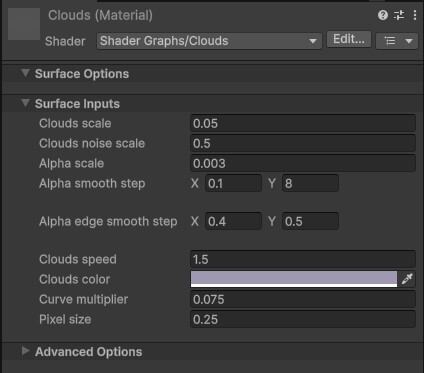
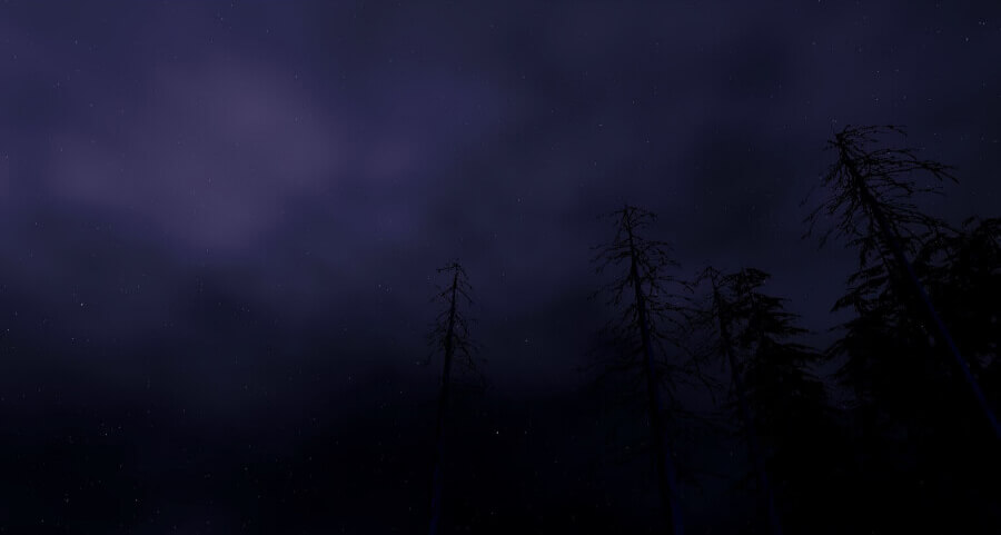
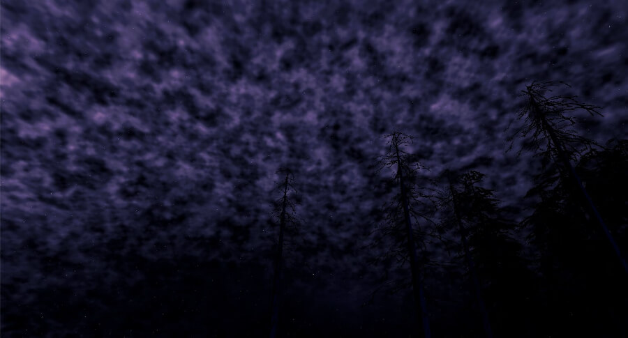
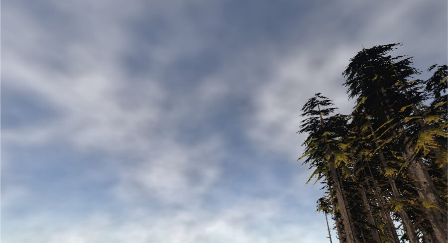
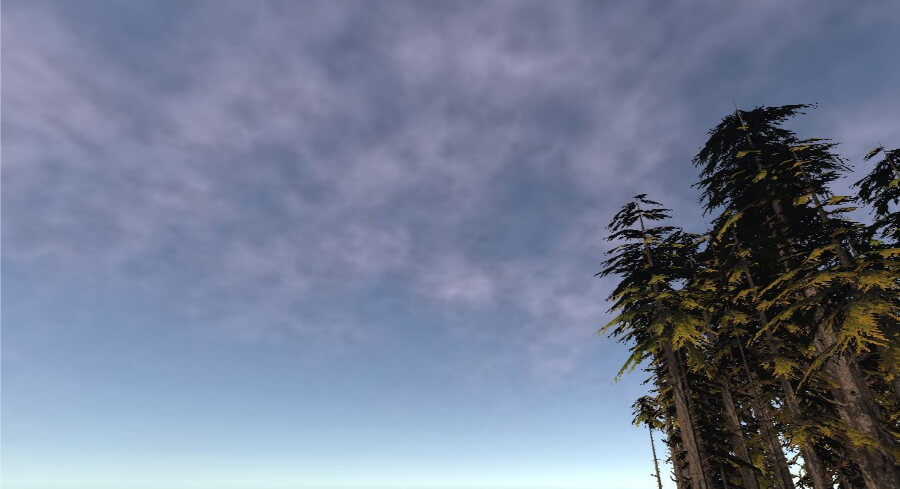
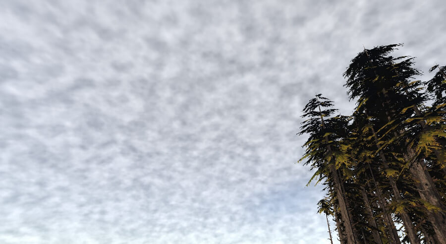
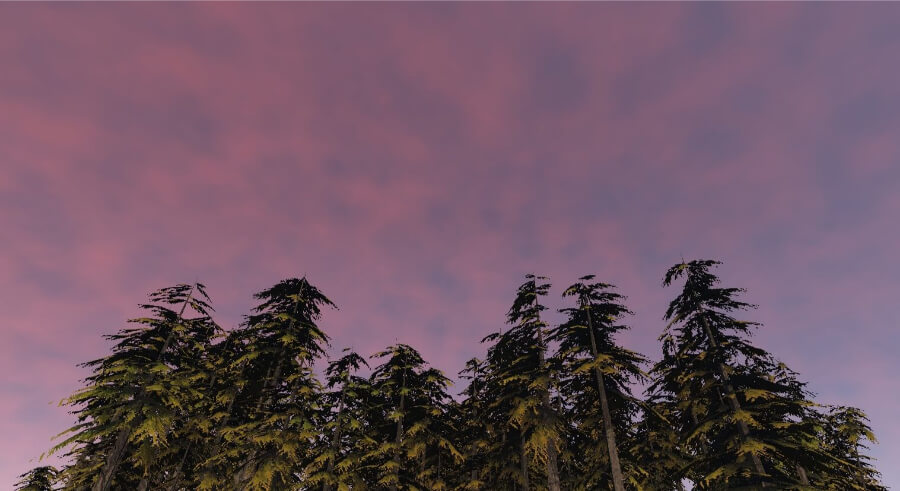
And there we go, our final material. Here are two values I used through this article, one for day time scenes and the other for night time scenes. As this is an unlit shader, the night time variant uses a much lower alpha (determined by the “Alpha smooth step”) value to make the clouds less bright.
From here you can do whatever you want. One neat trick to create a bit more depth is to add a second plane with a slightly different material. Perhaps one with faster moving clouds, less defined details, or anything else.
Thank you for reading <3